Sunday, December 4, 2016

Modbus Protocol part 4-Practical implementation

Implement Modbus Practically
USB is now commonly used to connect various kinds of devices to your computer. Before USB, devices are connected using  RS232 . An RS232 port on computers of the past would look like below figure, a simple 9-pin port.

 RS232 was designed mainly to connect modems to computers so that the latter could dial into mainframes. But soon RS232 spread to a host of different devices.
 One of the major drawbacks was that RS232 is point to point standard. In other words, all you could do is connecting one device to only one other. You could not connect one device to multiple devices to create a network of devices. In addition to this, RS232 could be used only up to a distance of about 50 feet, so transmission distance was a problem. It also was not very resistant to sources of electrical noise.
 So the RS485 electrical standard was therefore created. RS485 allows the connection of multiple devices to create a network. Up to 32 devices can be connected onto one multidrop RS485 connection. RS485 also allows transmission for up to 4000 feet and is very resistant to electrical noise. Hence it was able to overcome the problems that plagued RS232.
Modbus is a protocol, RS485 is a electrical standard. Modbus defines messaging structure used to exchange data.RS485 only defines the electrical signal levels and wiring that allow data to be transferred.
Not only RS485, Modbus can stick into many different electrical standards such as RS232,RS422,Radio signals etc.
If we consider a PLC there are
·         CPU
·         Memory
·         Communication
If we take a memory segment it has two parts Memory address and memory value.

There are memory blocks with various sizes. This size depends on the application. Size of the memory block is measured by bits.
Ø  1 bit for Discrete input (on/off)
Ø  8 bit for Analog input (eg.232 for RTD)

Ø  Below figure shows PLC with analog input.


Modbus memory areas

But what is meant by coils, inputs, input registers and holding registers?
NOTE-Modbus memory areas can be used to store data which results from various applications.
The link between inputs/outputs with related memory block is called mapping. For each product Manufacturers define how the mappings are done

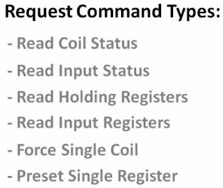
Modbus request commands

* I will explain about function codes later.

Modbus block read
Consider master device needs to read two memory blocks (10050 and 10057) in its slave device (ID 21)
The Read Input Status command only allows specifying a start memory block address and then the number of memory blocks to read from that start point. So in the case of the example, It would have to configure the Modbus master to send, as before, the Read Input Status command together with the  Modbus Unit Id of 21, but it would then specify a start memory block address of  10050 and a memory block length of 8.
So when this request is sent to the slave, the slave would return data for memory addresses 10050, 10051, 10052, 10053, 10054, 10055, 10056, 10057. The master would simply extract the data from 10050 and 10057 and ignore the remaining data sent back.

Physical connection

Every single device on the same RS485 network should have the exact same settings for their port parameters
·         Baud rate
·         Number of data bits
·         Number of stop bits
·         Parity

Friday, December 2, 2016

Modbus Protocol part 3

More into Modbus message structure

Address field

Address field contains two ASCII characters or 8 bits (RTU).Also we know that the valid slave addresses are in 0-247 range decimal.
·         In the response slave puts its own address in the address field to let the master know which slave is responding.

Function filed
The function field consists of two ASCII characters (ASCII) or 8 bits (RTU).In error free response the function code is similar to receive query. But if there is some error, the most significant bit of query function code is set to 1 in the response function field.
Ø  Example
Query function code=0000 0011
Error free response function code=0000 0011
If there is an error, response function code=1000 0011.
In erroneous situation slave puts unique code in to data field which describes the error occurred.

Data field
The data field is constructed using sets of two hexadecimal digits in the range of 00 to FF hexadecimal (pair of ASCII characters or one RTU character).In query, this data field contains discrete and register addresses, the quantity of items to be handled, the count of data bytes to follow in the data field and the data to be written in to registers.
If no error occurs response data field contains the requested data else it contains unique code which describes the error.

Error checking field
How Modbus does detect errors?
Standard Modbus serial networks use two kinds of error checking.

1.      Parity checking (even or odd) can be optionally applied to each character.
2.      Frame checking (LRC or CRC) is applied to the entire message.

Both the character check and message frame check are generated in the master device and applied to the message contents before transmission. The slave device checks each character and the entire message frame during receipt.

1.      Parity Checking
Users can configure controllers for Even or Odd Parity checking, or for No Parity checking. This will determine how the parity bit will be set in each character. If either Even or Odd Parity is specified, the quantity of 1 bits will be counted in the data portion of each character (seven data bits for ASCII mode, or eight for RTU).
The parity bit will then be set to a 0 or 1 to result in an Even or Odd total of 1 bit.

2.      Frame checking
IN ASCII mode there are two ASCII characters in the error checking field. The error check characters are the result of a Longitudinal Redundancy Check (LRC) calculation that is performed on the message contents, exclusive of the beginning ‘colon’ and terminating CRLF characters.

What is LRC?
The LRC field checks the contents of the message, exclusive of the beginning ‘colon’ and ending CRLF pair. It is applied regardless of any parity check method used for the individual characters of the message. The LRC field is one byte, containing an 8–bit binary value. The LRC value is calculated by the transmitting device, which appends the LRC to the message. The receiving device calculates an LRC during receipt of the message, and compares the calculated value to the actual value it received in the LRC field. If the two values are not equal, an error results.

In RTU mode error checking field has two bytes. The error check value is the result of a Cyclical Redundancy Check calculation performed on the message contents. The CRC field is appended to the message as the last field in the message. When this is done, the low–order byte of the field is appended first, followed by the high–order byte. The CRC high–order byte is the last byte to be sent in the message.

For more details refer Modbus official site.


Modbus Protocol part 2

In this post I will try to describe about master/slave configuration, Serial interface, Query-response cycle and transmission modes in the Modbus protocol.

What is master/slave technique?
There is only one device (master) which is requesting information and there can be many devices (Modbus slaves) that can supply requested information. In standard Modbus protocol there is a master and up to 247 slave device. Also master device can send information to slave devices. Each slave device has unique address from 1 to 247.

Examples for master and slaves
·         Master devices-Monitoring panels, servers
·         Slave devices-Mainly PLCs, VSDs


As I told earlier Modbus protocol defines structure of messages transmitting between master and slaves. The message send by master to any slave is called query and the message send by slave to master is called response.

A-What kind of action should be performed by the slave device
B-Any additional data needed to perform the function
C-To validate message contents
D- What kind of action should be performed by the slave device? If any error occurred the    function code of that error will be sent
E-Collected data
F- To validate message contents.

Transmission modes
We know that queries and responses are transmitting serially. But how does information pack in those messages and how to decode them???

There are two serial transmission modes
1.      ASCII mode
2.      RTU(Remote Terminal Unit) mode

ASCII mode
Before talking about this it is helpful to know about Modbus message framing. Above both transmitting modes Modbus message is framed. In this frame the beginning point and ending points are known. This frame has 8 bits.

Now let’s move into ASCII...We know that ASCII characters are represented by Hexadecimal Numbers. It is clear that 8 bits can represent 2 hexadecimal numbers. So There are two ASCII characters in one message. In this ASCIII transmission mode the time delay between there ASCII characters can be take time up to 1 second. That is main advantage of this method. If a greater interval occurs, the receiving device assumes an error has occurred.

Coding System: Hexadecimal, ASCII characters 0–9, A–F
One hexadecimal character contained in each
ASCII character of the message
Bits per Byte: 1 start bit
7 data bits, least significant bit sent first
1 bit for even/odd parity; no bit for no parity
1 stop bit if parity is used; 2 bits if no parity
Error Check Field: Longitudinal Redundancy Check (LRC)  *This will be discussed later.

In ASCII mode, messages start with a ‘colon’ ( : ) character (ASCII 3A hex), and
End with a ‘carriage return – line feed’ (CRLF) pair (ASCII 0D and 0A hex).


RTU Mode
Each 8 bit byte in a message contains two 4 bit hexadecimal characters.

Coding System: 8–bit binary, hexadecimal 0–9, A–F
Two hexadecimal characters contained in each
8–bit field of the message
Bits per Byte: 1 start bit
8 data bits, least significant bit sent first
1 bit for even/odd parity; no bit for no parity
1 stop bit if parity is used; 2 bits if no parity
Error Check Field: Cyclical Redundancy Check (CRC) *This will be discussed later

Let’s move into RTU framing
In RTU mode messages start with a silent interval of at least 3.5 character time. The entire message is transmitted in continuous stream. The figure shows the RTU frame. One frame should transmit without having time interval of less than or equal  1.5 character time between each fields(slave address, data Error check, Function code).If this condition is not satisfied received data will be discarded.

Important – It can be seen that in RTU mode there no dedicated bits to indicate start and end of a message. That is indicated by using specific time interval (3.5 character time).Therefore RTU mode has greater character density and hence has more data throughput.

The fields in a Modbus message will be discussed in next post.