Implement
Modbus Practically
USB is now commonly
used to connect various kinds of devices to your computer. Before USB, devices
are connected using RS232 . An RS232 port on computers of the past would
look like below figure, a simple 9-pin port.

RS232 was designed mainly to connect modems to computers
so that the latter could dial into mainframes.
But soon RS232 spread to a host of different devices.
One of the major drawbacks
was that RS232 is point to point standard. In other words, all you could do is connecting one device to only one other. You could not
connect one device to multiple devices to create a network of devices. In
addition to this, RS232 could be used only up to a distance of about 50 feet,
so transmission distance was a problem. It also was not very resistant to
sources of electrical noise.
So the RS485 electrical standard was therefore
created. RS485 allows the connection of multiple devices to create a network.
Up to 32 devices can be connected onto one multidrop RS485 connection. RS485
also allows transmission for up to 4000 feet and is very resistant to
electrical noise. Hence it was able to overcome the problems that plagued
RS232.
Modbus is a protocol, RS485 is a electrical standard.
Modbus defines messaging structure used to exchange data.RS485 only defines the
electrical signal levels and wiring that allow data to be transferred.
Not only RS485, Modbus
can stick into many different electrical standards such as RS232,RS422,Radio
signals etc.
If we consider a PLC
there are
·
CPU
·
Memory
·
Communication
If we take a memory
segment it has two parts Memory address and memory value.

There are memory blocks with various sizes. This
size depends on the application. Size of the memory block is measured by bits.
Ø 1
bit for Discrete input (on/off)
Ø 8
bit for Analog input (eg.232 for RTD)
Ø Below
figure shows PLC with analog input.

Modbus memory areas

But what is meant by
coils, inputs, input registers and holding registers?
NOTE-Modbus memory areas can be used to store data
which results from various applications.
The link between inputs/outputs with related memory
block is called mapping. For each product Manufacturers define how the mappings
are done
Modbus request commands
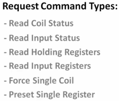
* I will explain about
function codes later.
Modbus block read
Consider master device needs to read two memory
blocks (10050 and 10057) in its slave device (ID 21)
The Read Input Status command only allows specifying
a start memory block address and then the number of memory blocks to read from
that start point. So in the case of the example, It would have to configure the
Modbus master to send, as before, the Read Input Status command together with
the Modbus Unit Id of 21, but it would
then specify a start memory block address of
10050 and a memory block length of 8.
So when this request is sent to the slave, the slave
would return data for memory addresses 10050, 10051, 10052, 10053, 10054,
10055, 10056, 10057. The master would simply extract the data from 10050 and
10057 and ignore the remaining data sent back.
Physical connection

Every single device on the same RS485 network should
have the exact same settings for their port parameters
·
Baud rate
·
Number of data bits
·
Number of stop bits
·
Parity
Very informative blog post. Here I found very useful information on Modbus protocol. Thanks for sharing valuable content.
ReplyDeleteThank you !
ReplyDelete