Soft Starter
Principle of operation
These power electronics starters or soft starters are made using thyristors; an electronic semiconductor which will conduct a continuous current when an input signal pulse is applied to its gate, and they help to regulate the energy consumed by the induction motor. When the thyristor is turned on initially and if there is an input sinusoidal signal, a voltage will be applied in to the motor where as if the thyristor is turned off the voltage goes to the motor will become zero. The unit is solid state, using a microprocessor to control inverse parallel (back to back) pairs of SCR's.An SCR/thyristor is a semiconductor device that latches when triggered. Once triggered it allows current to flow in one direction only and turns off at zero current. The firing angle of the SCR's are controlled to achieve the desired acceleration of the motor.The soft starter incorporates a closed loop torque control system to provide better control over starting & stopping 3 phase induction motors. Conventional voltage ramp control systems typically produce low torque at low speeds. When starting & stopping variable torque loads (e.g Pumps) this can results in a very rapid acceleration or deceleration with a nonlinear change in motor speed
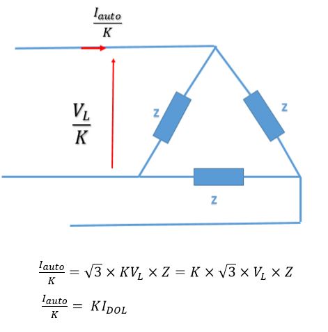
Circuit/Connection diagrams


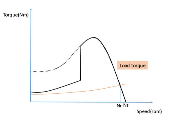
Characteristic curves during starting


Commercial products

Applications
- Pump applications where pressure surges should be avoided.
- Fans and other systems with belt drives to avoid belt slipping.
- Conveyor belt systems can be started very smoothly.
AC variable speed drive
Principle of operation
A variable speed drive is a piece of equipment that regulates the speed and rotational force, or torque output, of an electric motor. Control can mean either manually adjustable - by means of a potentiometer or linear hall effect device, (which is more resistant to dust and grease) or it can also be automatically controlled for example by using a rotational detector such as a Gray code optical encoder.
In general, a VFD(Variable Frequency Drive) in its most basic configuration controls the speed of an induction or synchronous motor by adjusting the frequency of the power supplied to the motor.

When changing VFD frequency in standard low-performance variable-torque applications using Volt-per-Hertz (V/Hz) control, the AC motor's voltage-to-frequency ratio can be maintained constant, and its power can be varied, between the minimum and maximum operating frequencies up to a base frequency. Constant voltage operation above base frequency, and therefore with reduced V/Hz ratio, provides reduced torque and constant power capability.
Regenerative AC drives are a type of AC drive which have the capacity to recover the braking energy of a load moving faster than the motor speed (an overhauling load) and return it to the power system.
The VFD article provides additional information on electronic speed controls used with various types of AC motors.
Circuit/Connection diagrams

Characteristic curves during starting


Commercial products

Applications
- Sewage lift station
Sewage usually flows through sewer pipes under the force of gravity to a wet well location. From there it is pumped up to a treatment process. When fixed speed pumps are used, the pumps are set to start when the level of the liquid in the wet well reaches some high point and stop when the level has been reduced to a low point. Cycling the pumps on and off results in frequent high surges of electric current to start the motors that results in electromagnetic and thermal stresses in the motors and power control equipment, the pumps and pipes are subjected to mechanical and hydraulic stresses, and the sewage treatment process is forced to accommodate surges in the flow of sewage through the process. When adjustable speed drives are used, the pumps operate continuously at a speed that increases as the wet well level increases. This matches the outflow to the average inflow and provides a much smoother operation of the process
- Cooling tower fans
- Dusting fan in steel and iron industry
- Compressors in oil and gas industry